
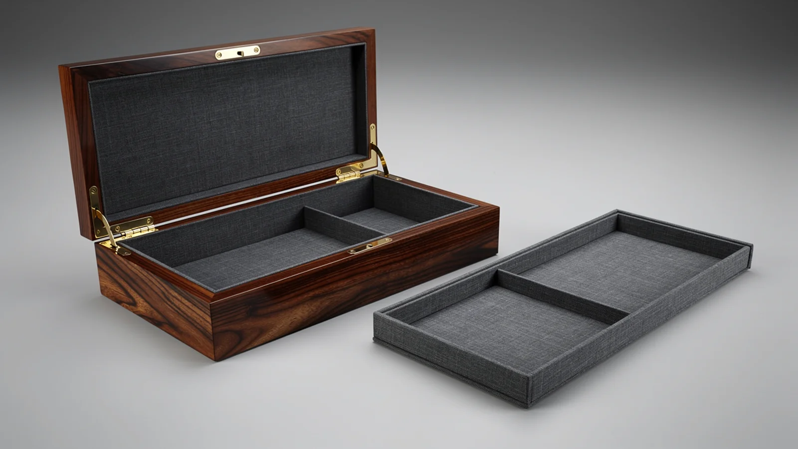

Start with the two surfaces that must fit
A box’s outside dimensions are useful for presentation, shelf space and outer packaging. They do not directly tell an insert supplier the available cavity. Draw the finished opening and the insert’s finished outer boundary as separate features. Identify where each dimension is taken and the direction in which the insert enters the box.
Use distinct names for bare shell size, lined cavity size and insert outer size. If the liner, fabric folds or hardware occupy part of the opening, define the usable boundary that matters to assembly. A measurement across the top opening may not answer whether a tray will reach its seating position farther down.
Specification insight: give the supplier a finished-space requirement, not just a subtraction from outside box dimensions. If cavity limits already describe the completed lining and assembly, do not subtract those same layers a second time in the fit calculation. Choose one consistent dimension chain and document it.
Product arrangement remains a separate input. A wine-box dimension plan establishes which bottles and accessories must be accommodated; the tolerance review then asks how the permitted part variations affect that arrangement. For a general project, start from the chosen wooden packaging box structure and mark its critical interfaces.
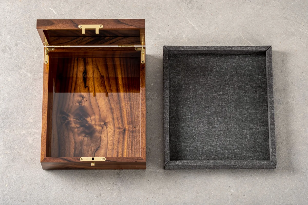
Keep nominal size, limits and clearance distinct
The College of New Jersey’s dimensioning and tolerancing teaching material defines tolerance as the difference between the upper and lower dimensional limits. In a symmetric plus/minus specification, the total tolerance range is therefore twice the stated deviation. This is different from the clearance between two parts.
| Term | What it describes | What to put on the brief |
|---|---|---|
| Nominal size | The named design size | Identify the feature and units |
| Dimensional limits | The permitted size interval | State the minimum and maximum, or an unambiguous equivalent |
| Total clearance | The difference between mating sizes | State the axis and whether the value is total or per side |
| Measurement uncertainty | Uncertainty associated with a measured result | Agree the method and handling of results near a limit |
Do not infer a production tolerance from the number of decimal places in a catalog description. On a controlled drawing, a general tolerance note may apply to otherwise untoleranced dimensions; that rule needs to be identified. A number copied into an email without its drawing notes loses that context.
Ask the supplier to flag dimensions that need a different acceptance method because they involve a compressible covering or an irregular feature. A single box-wide plus/minus note can hide these distinctions. Prioritize dimensions that affect assembly and agree other requirements separately.
A worked example: nominal clearance is only the starting point
The following is a hypothetical calculation, not a recommended wood-box tolerance or a statement of XRX manufacturing capability. Assume a finished cavity width of 260 ± 1 mm and a finished insert outer width of 258 ± 0.5 mm. Treat them as simple parallel boundaries measured along the same axis.
| Quantity | Lower limit | Upper limit |
|---|---|---|
| Finished cavity width | 259 mm | 261 mm |
| Finished insert outer width | 257.5 mm | 258.5 mm |
| Calculated total width clearance | 259 − 258.5 = 0.5 mm | 261 − 257.5 = 3.5 mm |
The nominal difference is 260 − 258 = 2 mm. The tightest allowed pairing is the smallest cavity with the largest insert; the loosest is the largest cavity with the smallest insert. This is why subtracting only the nominal sizes does not establish the fit range. The WisTech Open tolerance chapter explains that contributing tolerances accumulate even when dimensions are subtracted.
Here, 0.5–3.5 mm is the total width clearance. It is not a promised gap on each side. If an insert sits against one wall, the available gap is concentrated on the other side. An equal split assumes centering as well as parallel surfaces. A loose tray has no automatic mechanism that maintains that position.
The result does not tell you whether either extreme is acceptable. That requires a functional requirement: perhaps the tray must lift out easily while remaining visually aligned. Agree how to assess both the tight and loose conditions. Do not select a narrower component tolerance merely because it looks more precise on paper.
This range is also not a prediction of reject percentage. It describes the extrema permitted by the inputs under the stated geometry. It says nothing about how frequently production reaches them. Forecasting that frequency would require suitable production data and a separate statistical model.
What a width calculation leaves out
Check the insertion path, length, height and corners as well as width. A corner radius, a locally thick fabric fold or a projecting hardware part may obstruct movement even when a width measured elsewhere is acceptable. A tray that enters at the top but stops short of its intended seat has not passed the functional requirement.
Next, load the representative product and close the lid using the intended motion. Check caps, handles, raised decoration and any leaflet or accessory included in the final configuration. Record the product and accessory versions used for this loaded check; an empty assembly does not establish the same result.
For compressible inserts, agree whether a dimension is assessed without compression or under a defined measurement condition. Avoid pressing a soft edge until a convenient reading appears. The inspection method should represent the intended requirement and be repeatable between the buyer and supplier.
Treat these checks as a proposed design review, not proof of shipping performance. A fitted presentation tray may still need separate transport packaging. Likewise, this simple example does not model dimensional changes over time or different environments; record the measurement and use conditions relevant to the project.

Turn “fits well” into an acceptance brief
Use the following fields to make quotations and sample reviews comparable. Attach a marked drawing or photo identifying the measurement positions. If the box and insert come from different suppliers, issue the same interface revision to both and assign responsibility for checking the assembled result.
| Field | Information to agree | Reason |
|---|---|---|
| Finished configuration | Material, lining, covering and hardware revision | Defines what is included in the measured boundary |
| Critical dimensions | Cavity and insert limits at marked locations | Controls both sides of the interface |
| Measurement method | Reference faces, instrument and contact condition | Reduces disagreements about the reading |
| Functional fit | Insertion, seating, removal and loaded lid checks | Connects dimensions to actual use |
| Acceptance decision | Inspection plan and near-limit result handling | Defines how the order will be assessed |
| Change control | Changes that require renewed fit approval | Keeps later parts tied to the approved interface |
Measurement uncertainty belongs in that discussion. NIST’s measurement-uncertainty guidance identifies contributions from the measurement process, including instruments, observers and other conditions. A display with more decimal places does not by itself resolve these contributions. Agree how results near a limit will be reviewed instead of treating every displayed reading as exact.
Do not add an arbitrary uncertainty number to the drawing allowance to excuse a nonconforming part. The dimensional requirement and the confidence in a measurement are different issues. Where the decision is sensitive, ask the responsible quality or metrology specialist to establish an appropriate method and decision rule.
Approval insight: one attractive sample is a reference, not a demonstration of every allowed pairing. Record the actual dimensions of the approved golden sample and identify any tighter or looser conditions that need evaluation. Do not assume that a hand-adjusted sample demonstrates interchangeability across the order.
Before confirming production, resolve who checks the interface after a liner, insert covering or product revision changes. Keep the updated drawing and sample decision together. Contact XRX with the product files, intended box structure and critical fit requirements to develop a dimensioned sample brief.
Frequently asked questions
What is dimensional tolerance in a wooden box specification?
It defines the permitted variation of a stated dimension. Identify the feature, its finished condition and its upper and lower limits, rather than relying on a nominal size alone.
Is a 2 mm nominal clearance the gap in every finished box?
No. The actual total clearance depends on both the cavity size and the insert size. Calculate the smallest cavity minus the largest insert, and the largest cavity minus the smallest insert, to find the limits of a simple one-axis model.
Does total clearance mean the gap on each side?
No. Total width clearance is the cavity width minus the insert width. It divides equally between two sides only when the insert is centered and the relevant surfaces are parallel.
Should dimensions be measured before or after lining?
Specify the stage explicitly. For usable-space acceptance, measure the finished condition that the product or insert encounters, including the agreed lining, covering and installed components.
Does a fitting golden sample prove every production combination will fit?
No. It shows the approved sample condition. Define component limits, measurement methods and a production inspection plan, then assess the combinations and finished assembly relevant to the design.